Magneto-electro-mechanical coupling features interesting potential for sensing and control applications, primarily owing to the non-contact field effect of magnetics. Consider an electrical coil inserted with a permanent magnet (Figure 1, commonly referred to as electromagnetic acoustic transducer EMAT). When excitation current goes through the coil, harmonic magnetic field is generated, inducing eddy currents into the part of structure underneath, provided that the structural surface is electrically conductive. The eddy currents, moreover, can generate the Lorentz force under the static magnetic field of the permanent magnet. For example, when harmonic electrical current is applied to the coil, a harmonic Lorentz force is generated, leading to stationary waves in the structure. The resulting local vibration/oscillation, meanwhile, changes the distribution of the eddy currents induced, which will in turn affect the magnetic flux density through the coil and eventually change the voltage across the coil and the current. In other words, by measuring the current change in the coil, one can actually extract the structural impedance or admittance information. This non-contact magnetic admittance/impedance sensing mechanism (Figure 2) is promising for structural health monitoring.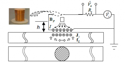
Figure 1. Magnetic sensor for impedance sensing
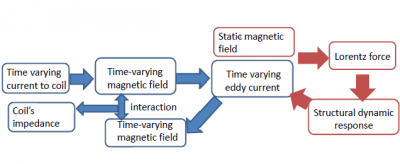
Figure 2. Multi-field coupling and impedance sensing mechanism
Building upon systemtic modeling and analysis of the two-way magneto-mechanical coupling, we develop some preliminary results to improve magnetic impedance sensing. In one study, we employ both the real-part and the imaginary-part of the magneto-mechanical impedance measured (Figure 3), and utilize their intrinsic relations with respect to the lift-off distance to effectively cancel out the random oscillation effect that is problematic in non-contact sensing. We define a transformed impedance. Around each resonant frequency at which the damage effect is most significant, we can calculate a constant scaling factor that can render the transformed impedance immune to the variation of lift-off distance during impedance measurement (Figure 4).
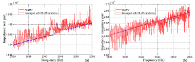
Figure 3. Impedance measurements before and after damage occurrence. (a) real part; (b) imaginary part. The impedance under damaged status is measured under lift-off distance oscillation (1 mm magnitude) induced by a shaker in the experiment. Damage effect cannot be seen.
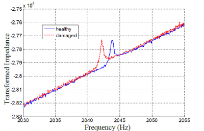
Figure 4. Comparison of transformed impedances: damage signature is clearly shown.
In another study, we integrate capacitance and negative resistance elements into the measurement circuit (Figure 5), and demonstrate that such integration can drastically amplify the damage features measured.
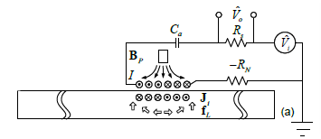
Figure 5. Enhanced magnetic sensor imtegrated with capacitor (to induced resonance) and negative resistence element (to cancel out inherent resistance).